Fourth_rotor
Enigma rotor details
Technical details about the Enigma machine
This article contains technical details about the rotors of the Enigma machine. Understanding the way the machine encrypts requires taking into account the current position of each rotor, the ring setting and its internal wiring.
This article has multiple issues. Please help improve it or discuss these issues on the talk page. (Learn how and when to remove these template messages)
|

| Exploded view of an Enigma rotor | Three rotors in sequence | ||
|---|---|---|---|
 |
|
 | |
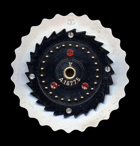 The right side of a rotor, showing the pin electrical contacts. The Roman numeral V identifies the wiring of the rotor.
 The left side of an Enigma rotor, showing the flat (plate) electrical contacts. A single turnover notch is visible on the left edge of the rotor.


No letter can map to itself, a cryptographic weakness caused by the same wires being used for forwards and backwards legs.
The effect of rotation on the rotors can be demonstrated with some examples.
As an example, let us take rotor type I of Enigma I (see table below) without any ring setting offset. It can be seen that an A is encoded as an E, a B encoded as a K, and a K is encoded as an N. Notice that every letter is encoded into another.
In the case of the reflectors, in this example Wide B is taken (Reflector B in the table below) where an A is returned as a Y and the Y is returned as an A. Notice that the wirings are connected as a loop between two letters.
When a rotor has stepped, the offset must be taken into account to know what the output is, and where it enters the next rotor.
If for example rotor I is in the B-position, an A enters at the letter B which is wired to the K. Because of the offset this K enters the next rotor in the J position.
With the rotors I, II and III (from left to right), wide B-reflector, all ring settings in A-position, and start position AAA, typing AAAAA will produce the encoded sequence BDZGO[citation needed].
The ring settings, or Ringstellung, are used to change the position of the alphabet ring relative to the internal wiring. Notch and alphabet ring are fixed together. Changing the ring setting will therefore change the positions of the wiring, relative to the turnover-point and start position.
The ring setting will rotate the wiring. Where rotor I in the A-position normally encodes an A into an E, with a ring setting offset B-02 it will be encoded into K
As mentioned before these encodings only happen after the key is pressed and the rotor has turned. Tracing the signal on the rotors AAA is therefore only possible if a key is pressed while the rotors were in the position AAZ and the ring settings are all on 01 or A.
With the rotors I, II, III (from left to right), wide B-reflector, all ring settings in B-position, and start position AAA, typing AAAAA will produce the encoded sequence EWTYX.
This table shows how the internal wiring connects the right side of the rotor (with the spring-loaded contacts) to the left side. Each rotor is a simple substitution cipher. The letters are listed as connected to alphabet order. If the first letter of a rotor is E, this means that the A is wired to the E. This does not mean that E is wired to A; such looped wiring is only the case with the reflectors.
- Terminology
- The reflector is also known as the reversing drum or, from the German, the Umkehrwalze or UKW.
| Rotor # | ABCDEFGHIJKLMNOPQRSTUVWXYZ | Date Introduced | Model Name & Number |
|---|---|---|---|
| IC | DMTWSILRUYQNKFEJCAZBPGXOHV | 1924 | Commercial Enigma A, B |
| IIC | HQZGPJTMOBLNCIFDYAWVEUSRKX | 1924 | Commercial Enigma A, B |
| IIIC | UQNTLSZFMREHDPXKIBVYGJCWOA | 1924 | Commercial Enigma A, B |
| Rotor # | ABCDEFGHIJKLMNOPQRSTUVWXYZ | Date Introduced | Model Name & Number |
| I | JGDQOXUSCAMIFRVTPNEWKBLZYH | 7 February 1941 | German Railway (Rocket) |
| II | NTZPSFBOKMWRCJDIVLAEYUXHGQ | 7 February 1941 | German Railway (Rocket) |
| III | JVIUBHTCDYAKEQZPOSGXNRMWFL | 7 February 1941 | German Railway (Rocket) |
| UKW | QYHOGNECVPUZTFDJAXWMKISRBL | 7 February 1941 | German Railway (Rocket) |
| ETW | QWERTZUIOASDFGHJKPYXCVBNML | 7 February 1941 | German Railway (Rocket) |
| Rotor # | ABCDEFGHIJKLMNOPQRSTUVWXYZ | Date Introduced | Model Name & Number |
| I-K | PEZUOHXSCVFMTBGLRINQJWAYDK | February 1939 | Swiss K |
| II-K | ZOUESYDKFWPCIQXHMVBLGNJRAT | February 1939 | Swiss K |
| III-K | EHRVXGAOBQUSIMZFLYNWKTPDJC | February 1939 | Swiss K |
| UKW-K | IMETCGFRAYSQBZXWLHKDVUPOJN | February 1939 | Swiss K |
| ETW-K | QWERTZUIOASDFGHJKPYXCVBNML | February 1939 | Swiss K |
| Rotor # | ABCDEFGHIJKLMNOPQRSTUVWXYZ | Date Introduced | Model Name & Number |
| I | EKMFLGDQVZNTOWYHXUSPAIBRCJ | 1930 | Enigma I |
| II | AJDKSIRUXBLHWTMCQGZNPYFVOE | 1930 | Enigma I |
| III | BDFHJLCPRTXVZNYEIWGAKMUSQO | 1930 | Enigma I |
| IV | ESOVPZJAYQUIRHXLNFTGKDCMWB | December 1938 | M3 Army |
| V | VZBRGITYUPSDNHLXAWMJQOFECK | December 1938 | M3 Army |
| VI | JPGVOUMFYQBENHZRDKASXLICTW | 1939 | M3 & M4 Naval (FEB 1942) |
| VII | NZJHGRCXMYSWBOUFAIVLPEKQDT | 1939 | M3 & M4 Naval (FEB 1942) |
| VIII | FKQHTLXOCBJSPDZRAMEWNIUYGV | 1939 | M3 & M4 Naval (FEB 1942) |
| Rotor # | ABCDEFGHIJKLMNOPQRSTUVWXYZ | Date Introduced | Model Name & Number |
| Beta | LEYJVCNIXWPBQMDRTAKZGFUHOS | Spring 1941 | M4 R2 |
| Gamma | FSOKANUERHMBTIYCWLQPZXVGJD | Spring 1942 | M4 R2 |
| Reflector A | EJMZALYXVBWFCRQUONTSPIKHGD | ||
| Reflector B | YRUHQSLDPXNGOKMIEBFZCWVJAT | ||
| Reflector C | FVPJIAOYEDRZXWGCTKUQSBNMHL | ||
| Reflector B Thin | ENKQAUYWJICOPBLMDXZVFTHRGS | 1940 | M4 R1 (M3 + Thin) |
| Reflector C Thin | RDOBJNTKVEHMLFCWZAXGYIPSUQ | 1940 | M4 R1 (M3 + Thin) |
| ETW | ABCDEFGHIJKLMNOPQRSTUVWXYZ | Enigma I | |
Technical comments related to Enigma modifications 1939-1945.
Swiss K
In 1941 it became known to the Swiss that some of their Enigma traffic was being read by the French. It was decided to make some design modifications.
- One of the modifications consisted in modifying the wheel stepping on the Swiss Army machine. The slow, left-hand wheel was made stationary during operation while the second wheel stepped with every key stroke.
- The third wheel and the UKW would step in the normal fashion with Enigma stepping for the third wheel.
- The stationary but rotatable left-hand wheel was meant to make up for the missing stecker connections on the commercial machine.
Swiss Army Enigma machines were the only machines modified. The surviving Swiss Air Force machines do not show any signs of modification. Machines used by the diplomatic service apparently were not altered either.
The single turnover notch positioned on the left side (plate connector side) of the rotor triggers the stepping motion by engaging the ratchet teeth of the wheel to the left. Later rotors had two turnover notches. The table below lists the turnover notch point of each rotor.
| Rotor | Notch | Effect |
|---|---|---|
| I | Q | If rotor steps from Q to R, the next rotor is advanced |
| II | E | If rotor steps from E to F, the next rotor is advanced |
| III | V | If rotor steps from V to W, the next rotor is advanced |
| IV | J | If rotor steps from J to K, the next rotor is advanced |
| V | Z | If rotor steps from Z to A, the next rotor is advanced |
| VI, VII, VIII | Z+M | If rotor steps from Z to A, or from M to N the next rotor is advanced |
Normalized Enigma sequences
In the following examples you can observe a normal step sequence and a double step sequence. The used rotors are (from left to right) I, II, III, with turnovers on Q, E and V. It is the right rotor's behavior we observe here (turnover V).
- Normal sequence:
- AAU — normal step of right rotor
- AAV — right rotor (III) goes in V—notch position
- ABW — right rotor takes middle rotor one step further
- ABX — normal step of right rotor
- Double step sequence:
- ADU — normal step of right rotor
- ADV — right rotor (III) goes in V—notch position
- AEW — right rotor steps, takes middle rotor (II) one step further, which is now in its own E—notch position
- BFX — normal step of right rotor, double step of middle rotor, normal step of left rotor
- BFY — normal step of right rotor
The introduction of the fourth rotor was anticipated because captured material dated January 1941 had made reference to the development of a fourth rotor wheel;[2] indeed, the wiring of the new fourth rotor had already been worked out.
On 1 February 1942, the Enigma messages began to be encoded using a new Enigma version that had been brought into use. The previous 3-rotor Enigma model had been modified with the old reflector replaced by a thin rotor and a new thin reflector. Breaking Shark on 3-rotor bombes would have taken 50 to 100 times as long as an average Air Force or Army message. It seemed, therefore, that effective, fast, 4-rotor bombes were the only way forward. Encoding mistakes by cipher clerks allowed the British to determine the wiring of the new reflector and its rotor.[2]
- "Enigma wiring". www.cryptomuseum.com. Retrieved 2022-06-09.
- Mahon 1945, p. 62
- Mahon, A. P. (1945), The History of Hut 8 1939–1945, Kew, Richmond, Surrey, TW9 4DU: National Archives, Reference HW 25/2
{{citation}}: CS1 maint: location (link)