Oil_shale_extraction_overview.png
Size of this preview:
800 × 522 pixels
.
Other resolutions:
320 × 209 pixels
|
640 × 418 pixels
|
1,024 × 669 pixels
|
1,352 × 883 pixels
.

|
This
diagram
image could be re-created
using
vector graphics
as an
SVG
file
. This has several advantages; see
Commons:Media for cleanup
for more information. If an SVG form of this image is available, please upload it and afterwards replace this template with
{{

vector version available

|

new image name

}}
.
It is recommended to name the SVG file “Oil shale extraction overview.svg”—then the template Vector version available (or Vva ) does not need the new image name parameter. |
Summary
| Description |
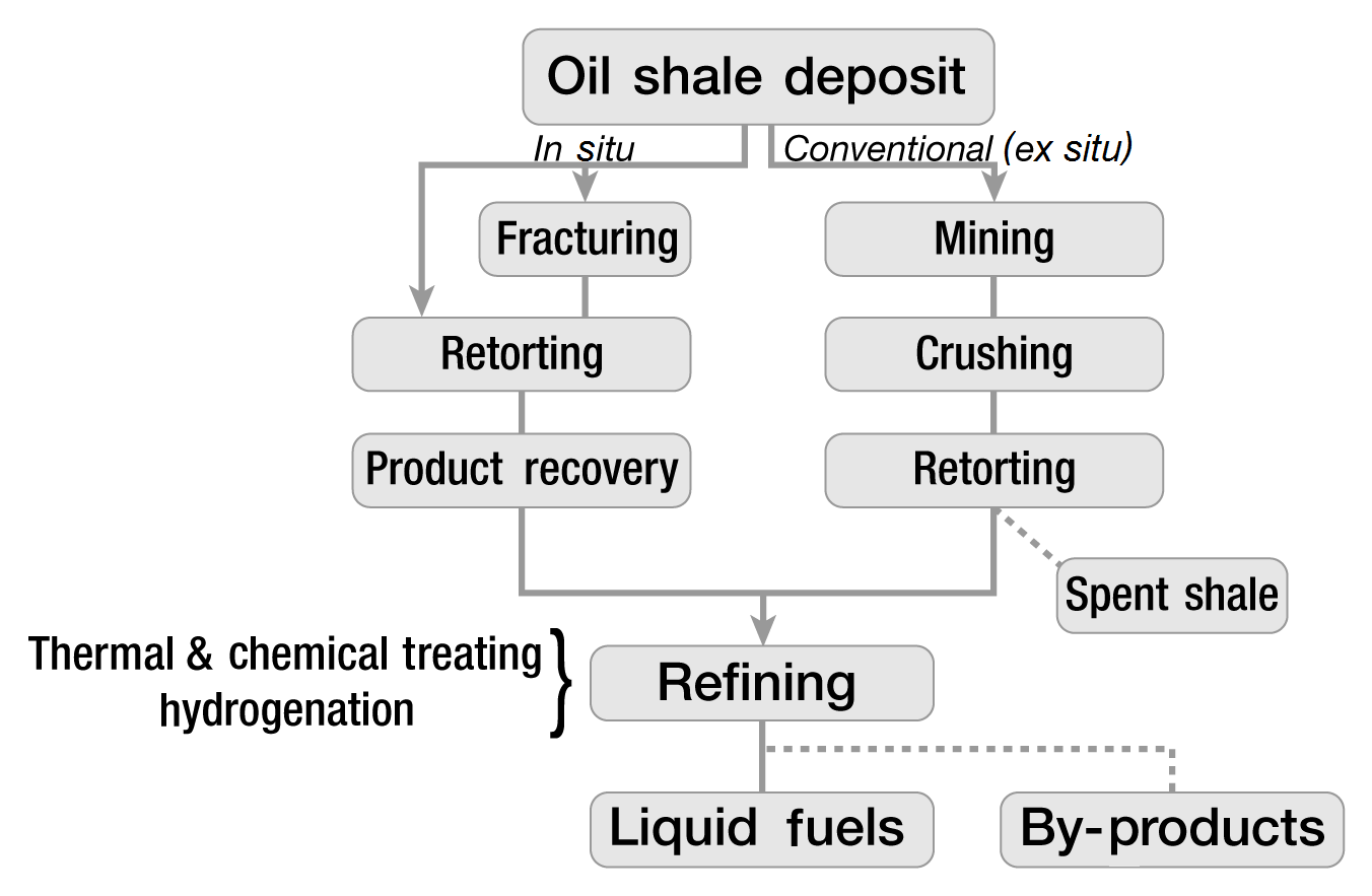
English:
Oil shale process diagram, some details removed by uploader
|
| Date | |
| Source | http://www.fossil.energy.gov/programs/reserves/npr/publications/npr_strategic_significancev2.pdf page 14 |
| Author | Office of Naval Petroleum and Oil Shale Reserves, U.S. Department of Energy |
| Other versions |
Derivative works of this file: Oljeskifferprocessering.PNG http://en.wikipedia.org/wiki/File:Oil_shale_extraction_overview.JPG |
Licensing
|
|
This image is a work of a
United States Department of Energy
(or predecessor organization) employee, taken or made as part of that person's official duties. As a
work
of the
U.S. federal government
, the image is in the
public domain
.
Please note that national laboratories operate under varying licences and some are not free . Check the site policies of any national lab before crediting it with this tag.
|

|