Optical_flat_interference.svg

Size of this PNG preview of this SVG file:
715 × 599 pixels
.
Other resolutions:
286 × 240 pixels
|
573 × 480 pixels
|
916 × 768 pixels
|
1,221 × 1,024 pixels
|
2,443 × 2,048 pixels
|
1,417 × 1,188 pixels
.
Summary
| Description |
English:
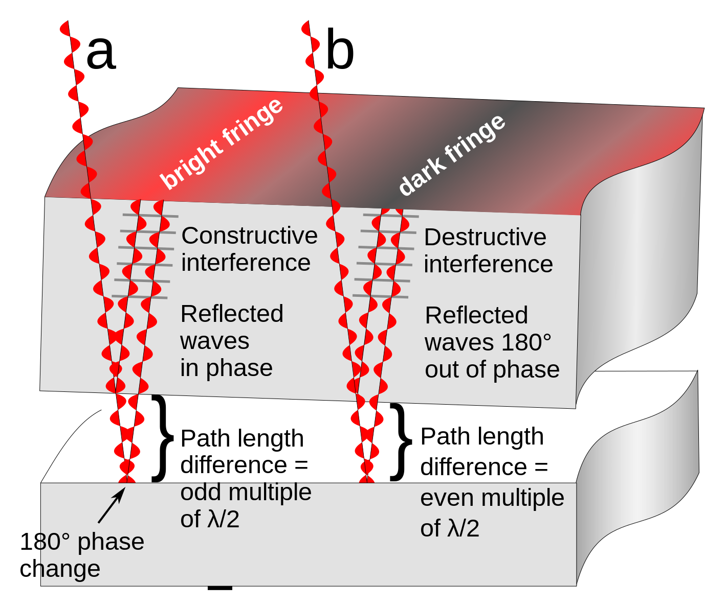
Diagram showing how
interference fringes
are created by an
optical flat
. The upper object is a section of a glass optical flat resting on another flat reflective surface. Light rays
(red)
from a monochromatic light source pass through the flat and reflect from both the bottom surface of the glass and the surface it is resting on. Since there is a tiny gap between the two surfaces, the ray reflecting off the bottom surface travels a greater distance than the top ray. It also experiences a 180° phase change at the reflection from the bottom plate (the reflection from the top plate causes no phase change). The parallel rays
superpose
. At locations
(a)
where the extra distance travelled by the 2nd ray (twice the width of the gap) is equal to an even multiple of a half-
wavelength
(λ/2)
of the light the two reflected waves will be in phase and will add, reinforcing each other, resulting in a bright reflected ray. This is called
constructive interference
. At other locations
(b)
the path difference between the rays is equal to an odd multiple of λ/2, so the reflected waves are 180° out of phase. They subtract, canceling each other out, resulting in little or no reflected light. This is called
destructive interference
.
When the two surfaces are not parallel, as in the diagram, this results in a pattern of alternating bright and dark bands visible on the surface, called interference fringes. Two adjacent interference fringes represent a difference in height of the surface of one-half wavelength of the light used, so interference patterns can be used to measure the flatness of surfaces to millionths of an inch. In this diagram the width of the gap and the wavelength of the light waves is greatly exaggerated; light has wavelengths around 10 -7 meter.
Русский:
Интерференция в тонком воздушном клине
|
| Date | |
| Source | Own work |
| Author | Chetvorno |
| Other versions |
|
| SVG development |
This diagram was created with
Inkscape
, or with something else
.
This diagram uses
translateable
embedded
text.
|


Licensing
I, the copyright holder of this work, hereby publish it under the following license:
|
|
This file is made available under the Creative Commons CC0 1.0 Universal Public Domain Dedication . |
|
The person who associated a work with this deed has dedicated the work to the
public domain
by waiving all of their rights to the work worldwide under copyright law, including all related and neighboring rights, to the extent allowed by law. You can copy, modify, distribute and perform the work, even for commercial purposes, all without asking permission.
|