Superheterodyne_receiver_block_diagram_2.svg

Size of this PNG preview of this SVG file:
800 × 254 pixels
.
Other resolutions:
320 × 102 pixels
|
640 × 203 pixels
|
1,024 × 326 pixels
|
1,280 × 407 pixels
|
2,560 × 814 pixels
|
2,243 × 713 pixels
.
Summary
| Description |
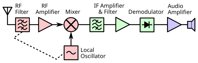
English:
Block diagram of a single conversion
superheterodyne radio receiver
. Invented by
Edwin Armstrong
in 1918 during World War 1, the superheterodyne is the design used in almost all modern
radio receivers
. The incoming radio signal from the antenna
(left)
is passed through an RF filter to attenuate some undesired signals, amplified in a radio frequency (RF) amplifier, and
mixed
with an unmodulated sine wave from a
local oscillator
. The result is a "beat" frequency or
heterodyne
at the difference between the input signal and local oscillator frequencies, a lower frequency called the
intermediate frequency
. The IF signal selected and strengthened by several IF stages that bandpass filter and amplify the signal. The IF signal is then applied to a
demodulator
that extracts the
modulated
audio
signal. An audio amplifier further amplifies the signal, and the speaker makes it audible.
. Superheterodyne receiver block diagram.svg is identical to this image except it doesn't show the image rejection filter |
| Date | |
| Source | Own work |
| Author | Chetvorno |
Licensing
I, the copyright holder of this work, hereby publish it under the following license:
|
|
This file is made available under the Creative Commons CC0 1.0 Universal Public Domain Dedication . |
|
The person who associated a work with this deed has dedicated the work to the
public domain
by waiving all of their rights to the work worldwide under copyright law, including all related and neighboring rights, to the extent allowed by law. You can copy, modify, distribute and perform the work, even for commercial purposes, all without asking permission.
|