Two_slider_crystal_radio_circuit.svg

Size of this PNG preview of this SVG file:
382 × 417 pixels
.
Other resolutions:
220 × 240 pixels
|
440 × 480 pixels
|
703 × 768 pixels
|
938 × 1,024 pixels
|
1,876 × 2,048 pixels
.
Summary
| Description |
English:
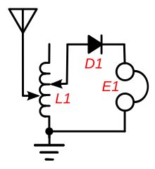
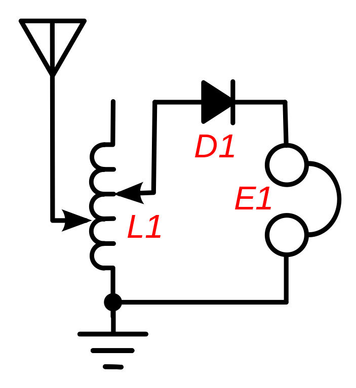
Circuit of a "two-slider"
crystal radio
receiver, a popular circuit used in simple crystal radios made before 1920. To tune in different stations, it used a tuning coil
(L1)
with two sliding contacts on it. It doesn't use a tuning capacitor, instead the coil resonates with the capacitance of the long wire antenna to create a tuned circuit. The left-hand slider tunes the receiver to different stations, allowing more or less of the coil's turns in parallel with the antenna capacitance. The right-hand slider adjusts the impedance match between the antenna and the rest of the circuit, to maximise the power transferred from the antenna into the receiver. It is adjusted until the station sounds loudest in the earphone
(E1)
. The coil acts as an impedance matching transformer to match the low impedance (10-200 ohms) of the antenna-ground circuit with the higher impedance (thousands of ohms) of the coil at resonance. The two adjustments were interactive, so adjusting the right slider also detuned the radio, requiring retuning.
|
| Date | |
| Source | Own work |
| Author | Chetvorno |
| SVG development |
This diagram was created with
Inkscape
, or with something else
.
This diagram uses
translateable
embedded
text.
|
Licensing
I, Chetvorno , the author of this work, release it into the public domain for any use whatever
|
|
I, the copyright holder of this work, release this work into the
public domain
. This applies worldwide.
In some countries this may not be legally possible; if so: I grant anyone the right to use this work for any purpose , without any conditions, unless such conditions are required by law. |