Wireless_power_system_-_capacitive_bipolar.svg

Size of this PNG preview of this SVG file:
800 × 419 pixels
.
Other resolutions:
320 × 167 pixels
|
640 × 335 pixels
|
1,024 × 536 pixels
|
1,280 × 670 pixels
|
2,560 × 1,340 pixels
|
1,179 × 617 pixels
.
Summary
| Description |
English:
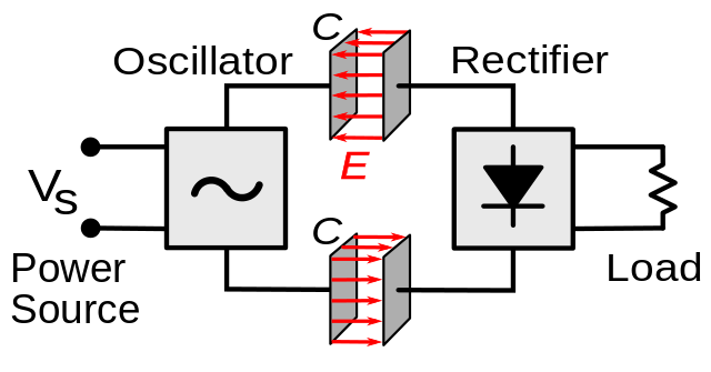
Generic block diagram of a
wireless power
system that works by
capacitive coupling
. It consists of a transmitter unit
(left)
that transmits power to a receiver unit
(right)
. The transmitter consists of an
electronic oscillator
that drives two
capacitor
plates
(C)
180° out of phase with a high frequency voltage. The alternating potential on the lefthand transmitter capacitor plates creates oscillating
electric fields
(E, red)
that induce alternating
potentials
on the righthand receiver capacitor plates by
electrostatic induction
. The potentials drive current back and forth through the
rectifier
which rectifies it to a direct current which powers the load.
|
| Date | |
| Source | Own work |
| Author | Chetvorno |
| Other versions |

|
Licensing
I, the copyright holder of this work, hereby publish it under the following license:
|
|
This file is made available under the Creative Commons CC0 1.0 Universal Public Domain Dedication . |
|
The person who associated a work with this deed has dedicated the work to the
public domain
by waiving all of their rights to the work worldwide under copyright law, including all related and neighboring rights, to the extent allowed by law. You can copy, modify, distribute and perform the work, even for commercial purposes, all without asking permission.
|